A short history | My radio background | Homemade radios | Tube radios
Transistor radios | World band radios | Kit radios | Reel tape recorders
My other interests | Pictures of Lebanon | Radio links
Home | Showcase | About this site

This is an 11 transistor-8 IC dual-conversion superheterodyne receiver which covers the broadcast and amateur (ham) frequencies from 5.7 to 22 MHz in 8 bands, and demodulates AM (amplitude modulation) and SSB (single side band) signals. The receiver is equivalent to 8 crystal-controlled switchable converters preceding a single-conversion system with a tuning range of 700 khz. The receiver has the following features: a double-tuned RF (radio frequency) amplifier with independent tuning for high sensitivity, high image selectivity, and accurate tracking; a crystal-controlled first oscillator for high stability; 2 balanced mixers for low spurious response; an independent VFO (variable frequency oscillator) with temperature-compensating capacitors for low frequency drift; 2 mechanical filters for high channel selectivity in AM and SSB modes; a two-stage IF (intermediate frequency) amplifier with AGC (automatic gain control) for high dynamic range, 2 selectable AGC speeds in AM and SSB modes, an active product detector with strong signal handling capabilities, a variable BFO (beat frequency oscillator) for easier SSB copying, and a signal (S) meter to show signal strength and simplify tuning and peaking. The receiver runs on 12 volts DC (direct current) and performs as good as or better than portable shortwave receivers on the market.
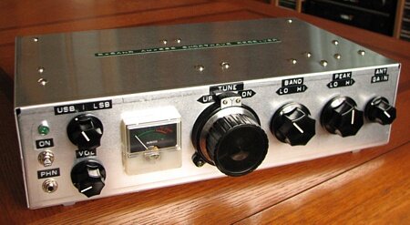 Dimensions: 12"(L) X 7"(D) X 3.25"(H). Controls from right: Antenna gain, RF Peak, Band, Tune, Volume(down), BFO(up) and ON/OFF switch. Lighted S-meter is left of tuning control. Green LED above switch indicates power ON. Phones jack is below switch. A 7:1 vernier dial offers smooth and accurate tuning.
 Back of receiver. From right: power jack, AM/SSB mode switch, Slow/Fast AGC switch, 2.5khz/5khz filter switch, digital display ON/OFF switch and jacks, antenna/ground connections and antenna amp. ON/OFF switch. The 2.5 and 5 KHz filters are used in SSB and AM modes respectively. A digital display is connected to the RCA jacks and powered from an outer unit.
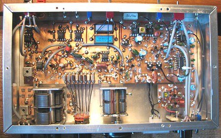 Inside the receiver. The circuitry was built "Manhattan" style, with round pieces of PCB glued to the main board and used to connect and hold the components. The main board used as a common ground. All stages where built on a single board, except the RF amp. and BFO modules, which have their own boards (left and right respectively). The 8 crystals which determine the bands are between the peaking capacitor (left) and the tuning capacitor (right). Shielded cable was used to carry RF and AF signals throughout.
 The receiver tuned to a broadcast station. The lighted S-meter helps in tuning and peaking, and gives a nice hi-tech look to the receiver. A mono to stereo adapter is used to allow stereo headphones to be used with the receiver.
A short history | My radio background | Homemade radios | Tube radios
Transistor radios | World band radios | Kit radios | Reel tape recorders
My other interests | Pictures of Lebanon | Radio links
Home | Showcase | About this site